

This article describes the results of the simulation of the generator oscillations in the Advanced Design System (ADS). ADS system contains all the functions that are necessary for the development and design of analog and digital radio devices, only the signal chain devices, wired or wireless, design and routing of printed circuit boards, the development of monolithic integrated circuits and three-dimensional electromagnetic structures. This system is good to use when organizing specialized labs on computer modeling of the technical subjects. We use ADS for simulation of chaos generators.
Introduction. Chaotic signals have the most information capacity, that is, their information entropy is maximized. This property of chaotic signals making them the most promising for the broadband wireless communication [1, 2]. As the systems that produce chaotic oscillations using nonlinear dynamic circuits, such as a generator Chua, the generator Pikovsky-Rabinovich [3], a generator with inertial nonlinearity Anischenko-Astakhov [4] and many other schemes. In this paper we present some results on the construction of the electronic circuit of the generator dynamic chaos (GDH) in the specialized program Advanced Design System (ADS) [5].
Advanced Design System
Advanced Design System is the world’s leading electronic design automation software for RF, microwave, and high speed digital applications. Here are some of ADS analysis:
- DC analysis: is used for determining the bias point of the circuit.
- Transient analysis: runs the time domain analysis on the circuits and considers the nonlinearity of the elements.
- AC analysis: runs the small signal analysis and use the linear model of elements on their bias point.
So the nonlinear elements like transistor are replaced by a linear model (small signal circuit) which includes resistors, capacitors, inductors and voltage & current sources.
– S_parameters analysis: calculates the Scattering parameters of the components, and shows the variation of the S_parameters over different frequencies. It is also used for calculating noise figure and group delay.
Fig. 1 shows the structure of the system ADS.
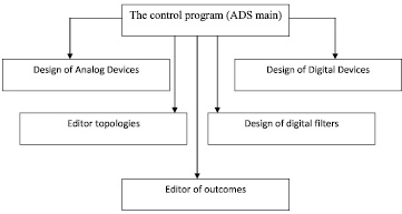
Fig. 1. Structure of the system ADS
Design of analog devices is provided by the subsystem RFIC Designer, the main features of which are:
- designing various classes of analog devices (mixers, amplifiers, filters, PLL, etc.);
- the use of different modeling techniques – the harmonic balance analysis on the AC and DC power, the analysis of S-parameter analysis method Circuit Envelope etc.
Design of digital devices is provided by the subsystem DSP Designer. The main features of the subsystem are:
- designing different classes of digital devices;
- the use of more than 900 models of functional blocks;
- co-simulation with analog RF devices;
- a user from creating their own models and their inclusion in the library of elements;
- the use of models for hardware description languages;
- synthesis of digital filters;
- library for modeling digital communication systems: GSM, CDMA, W-CDMA, EDGE, W-LAN, etc.;
- testing capabilities;
- getting VHDL and Verilog descriptions for the original scheme;
- ability to design digital filters;
- integration with Altera, Xilinx, Mentor Graphics, Texas Instruments, MatLab.
All design work must be done in a project directory. Working in project directories enables you to organize related files within a predetermined file structure. This predetermined file structure consists of a set of subdirectories. These subdirectories are used in the following manner:
- networks contains schematic and layout information, as well as information needed for simulating;
- data is the default directory location for input and output data files used or generated by the simulator;
- mom_dsn contains designs created with the Agilent EEsof planar electromagnetic simulator, Momentum;
- synthesis contains designs created with DSP filter and synthesis tools;
- verification contains files generated by the Design Rule Checker (DRC), used with Layout.
In Fig. 2 shows the front page ADS.
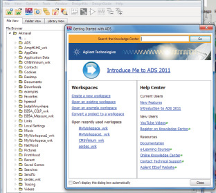

Fig. 2. A front page ADS
Assembly of electronic circuit diagram generator
Develop a model for the simulation of the microwave generator in the ADS package is to assemble the oscillator circuit, when we select the type of transistor, specify parameter, values resistor, capacitors and inductors [6].
The typical structure of the generator of chaotic oscillations consists of active and passive elements. As an active member protrudes oscillators with one freedom, usually in such oscillators chaotic oscillations do not occur. Passive oscillator is the second element of the structure. It also contains both linear and nonlinear elements with frequency selective properties. In general, the system began to generate chaotic oscillations when it must have at least 1,5 freedom.
The object of investigation is taken oscillator with an active element of the three-point scheme [27]. At microwave frequencies in the package ADS collected three points generator circuit shown in Fig. 3.
We have modeled such a generator and got the frequency response. In Fig. 4 shows the frequency response of the generator.
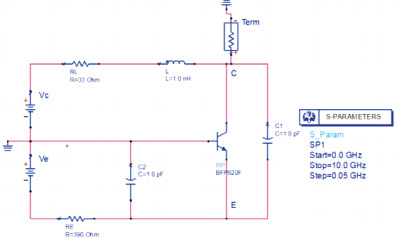
Fig. 3. The oscillator circuit of three points
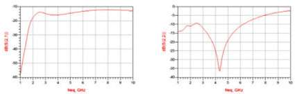
Fig. 4 shows the frequency response of the generator
The graphs show that a generator circuit can be regarded as a low pass filter, activated bipolar transistor.
The work is submitted to the International Scientific Conference «Implementation of integrated model of educational institutions, implements educational programs different levels of education», Republic of Singapore, December, 10-17, 2013, came to the editorial office оn 18.11.2013.